Vibration-Resistant Pipe Flange Bolting: Hydraulic Tensioning and Joint Integrity
On a compressor skid, a pump discharge, a relief-valve header, or a turbine-bound line, the flanged joint on the drawing looks identical to any other flange. In service, it is nothing of the kind. Continuous pulsation, flow-induced vibration, thermal cycling, and nearby rotating equipment attack the bolt load from the first day of operation. A joint correctly tightened at commissioning can lose a meaningful share of its preload within months, and once preload drops below the required gasket seating stress, the joint leaks — often at a point where a leak means an environmental release, a trip, or a safety incident.
Vibration-resistant flange bolting is therefore not a single product. It is a system: the right fastener material for the service, a locking method that works under dynamic load, a tightening method that delivers accurate and uniform preload, and an inspection regime that catches loss of load before it becomes a leak. This guide walks through that system for engineers, EPC procurement teams, and maintenance leads on Middle East and wider MENA oil, gas, petrochemical, and power projects.
1. Why Flange Joints Leak Under Vibration
A bolted flange joint works by keeping the gasket compressed. The studs stretch elastically, the nuts push back, and the clamp load on the gasket holds the sealing surfaces together against internal pressure, bending moments, and external loads. As long as the remaining clamp load stays above the minimum required gasket seating stress — and above the operating load under internal pressure — the joint stays tight.
Vibration attacks that equilibrium in several ways: transverse slip between the flange faces perpendicular to the bolt axis is the most common loosening mechanism — once friction under the nut is overcome, the bolt unwinds a fraction of a thread, repeatedly, thousands of times per minute. It is joined by embedment relaxation (gasket and surface asperities flattening), differential thermal expansion across cycling legs, and flow- or acoustic-induced vibration on thin-wall piping downstream of control valves.
The result is a joint that passed the initial leak test but begins weeping six months later. The fix is rarely "tighten it more." The fix is to design the joint — and the bolting method — so that the required preload is established accurately at installation and retained in service.
For a starting point on the fastener side of that joint, our overview of oil and gas fastener manufacturing and supply covers how stud-bolt packages are built, documented, and delivered to project QA/QC.
2. Fastener Materials: B7, B7M, L7, L7M and Service Selection
Before choosing a locking device or a tensioning method, the stud itself has to survive the environment. The material grade is selected from the service condition, not from the flange size:
| Service condition | Typical stud grade | Typical nut grade | Notes |
|---|---|---|---|
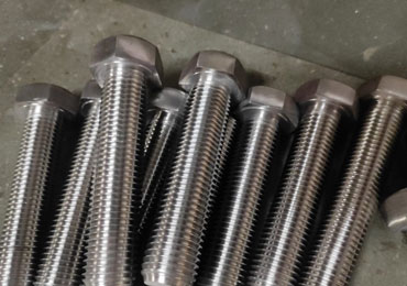
| General hydrocarbon service, up to roughly 425–450 °C | ASTM A193 B7 | ASTM A194 2H | Cr-Mo alloy steel, quenched and tempered |
| Low-temperature carbon steel service | ASTM A320 L7 | ASTM A194 7 | Charpy-impact tested for sub-zero service |
| Sour / H₂S service (carbon steel) | ASTM A320 L7M or A193 B7M | A194 7M / 2HM | Hardness controlled, typically ≤ 22 HRC per NACE MR0175 / ISO 15156 |
| High-temperature, long-term creep service | A193 B16 or A453 660 | Matching nuts | Vanadium-modified or austenitic, for high-temperature flanges |
| Corrosion / chloride service | A193 B8M Cl.2 (316) | A194 8M | Strain-hardened austenitic for consistent preload |
| Severe corrosive / subsea / seawater | Duplex F51 / super duplex F55 | Matching duplex | Per project CRA specification |
A few rules prevent the most common specification errors:
- B7M is not "softer B7." It is B7 produced to a hardness ceiling and is intended for sour service. Using B7 in H₂S service risks sulfide stress cracking; using B7M in non-sour service is usually unnecessary and adds cost.
- Match nut hardness and material to the stud. A194 nuts are selected per grade, and a nut that is too hard or too soft will gall or back off under load.
- State the edition and the supplementary requirements. Many Middle East projects invoke additional PMI, Charpy, and hardness testing beyond the baseline ASTM requirement. The purchase order should name them.
- For sour service specifically, the entire bolting system — studs, nuts, washers, and any coating — must comply with NACE MR0175 / ISO 15156. We cover this in more depth in the companion guide to sour-service fasteners and NACE MR0175 practice.
3. Locking Methods Compared: Spring Washers, Wedge-Locking, Prevailing Torque
Once the material is right, the next question is how to keep the nut from turning. Three approaches dominate industrial flange practice:
3.1 Spring and split lock washers
The familiar split spring lock washer is cheap and universally available. Under vibration, however, it has a well-documented weakness: once flattened, it offers almost no residual tension, and its sharp edges can dig into the flange surface, creating a pivot point that actually accelerates backing-off. In transverse-vibration testing (the Junkers-style test now used widely in fastener qualification), standard spring washers perform poorly. They are acceptable for low-stakes auxiliary joints; they are not recommended for critical process flanges subject to pulsation.
3.2 Wedge-locking washers
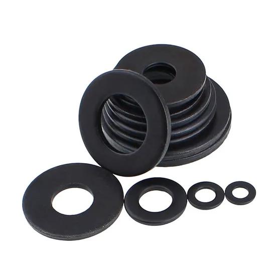
Wedge-locking washers (sold under various brand names) consist of two washers with a cam face on one side and a radial serration on the other. The cam angle is steeper than the bolt thread pitch, so any attempt to rotate the bolt lifts the cam pair rather than unwinding the thread — the serrations bite into the flange and nut faces, and the bolt can only turn by stretching further. Under transverse vibration, wedge-locking systems retain preload far better than split washers and are a common choice for pump, compressor, and valve flanges where a dedicated locking method is required. They are typically supplied as matched pairs, hardened, and must be sized to the bolt diameter and used with a suitably flat flange surface.
3.3 Prevailing-torque and chemical locking
Prevailing-torque nuts (e.g., nylon-insert or all-metal lock nuts) introduce a deliberate friction in the free-running portion of the nut. They work well on smaller, lower-load joints but are less common on heavy flanged process piping, where the preload is so high that the prevailing torque is a small fraction of the total and is difficult to control reliably. Thread-locking adhesive applied to the stud threads is an option for certain non-sour, accessible joints, but it complicates future disassembly and is generally not the primary strategy on large ASME B16.5/B16.47 process flanges.
3.4 The honest summary
For critical vibrating flanges, the most robust combination is usually: correctly tensioned studs with uniform preload, matched hardened washers under the nut, and wedge-locking washers where the joint specification calls for a mechanical locking device. Locking devices do not compensate for poor preload — they preserve the preload you already established. That is why the tightening method matters so much.
4. Torque Wrench vs. Hydraulic Tensioning: When Each Is the Right Tool
Two methods are used to stretch studs on process flanges: torqueing and hydraulic tensioning. They are not interchangeable, and choosing the wrong one is a leading cause of uneven preload and flange leakage.
4.1 Torqueing
A torque wrench (hydraulic torque wrench, typically, on process flanges) applies a turning force to the nut. Part of that torque stretches the bolt; the rest is consumed overcoming friction between the nut face, the flange, and the threads. The relationship between applied torque and resulting bolt load is expressed through the K-factor:
T = K × D × F
where T is torque (N·m or ft·lbf), D is bolt diameter, and F is the target bolt load. Because friction dominates, the K-factor is highly sensitive to lubrication, surface condition, plating, and thread fit. A typical K-factor for dry as-phased B7 studs is around 0.20; with a consistent lubricant it can drop to 0.12–0.14 and nearly double the resulting preload at the same torque reading. This is the central weakness of torqueing: small changes in lubrication produce large changes in actual bolt load.
Torqueing works well for smaller flanges, for joints where access is limited, and for routine bolt-up of standard piping. It is also the method most familiar to field crews.
4.2 Hydraulic tensioning
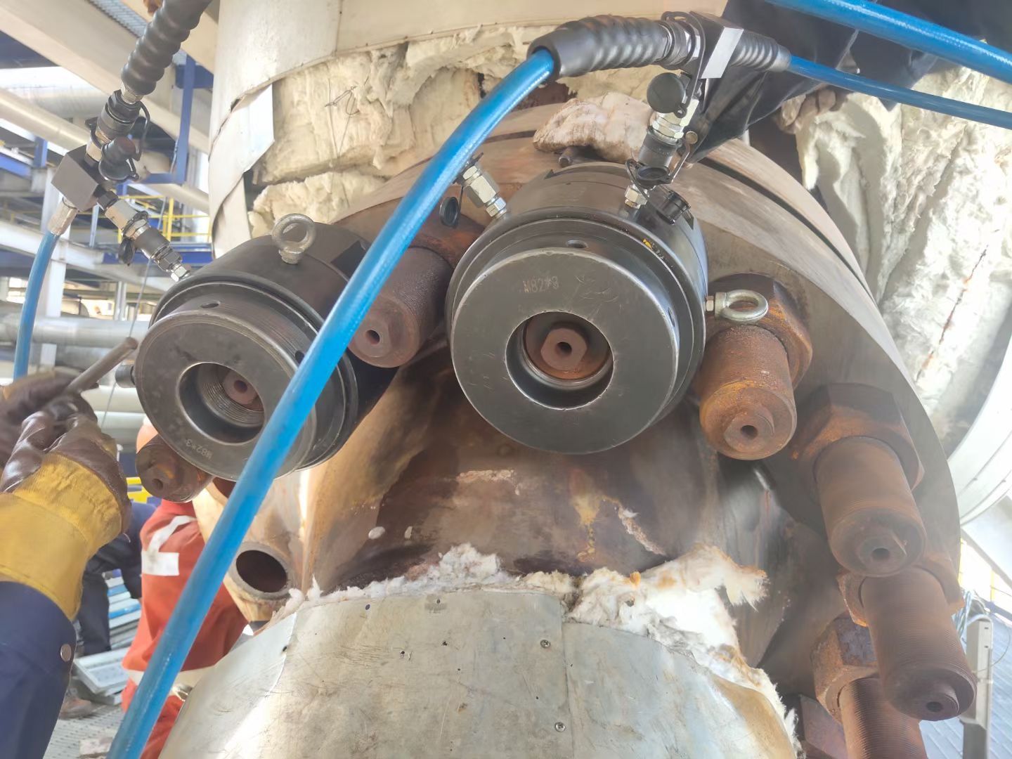
Hydraulic tensioning pulls the stud directly. A tensioner mounted over the stud uses a hydraulic cylinder to stretch the stud axially, and the nut is then run down to the flange face while the stud is held in tension. When the pressure is released, the stud is left stretched and the joint is clamped.
Because the stud is stretched directly, hydraulic tensioning eliminates friction from the preload equation — bolt load is set by hydraulic pressure and piston area, not by a torque-to-load relationship. It delivers more uniform load across the joint (tensioners can be installed on multiple studs simultaneously and pressurized together, the standard practice on large class 900, 1500, and 2500 flanges), reduces side load on the flange and gasket, and is faster on large joints: a multi-tensioner simultaneous operation can complete a bolt-up in minutes rather than hours.
The trade-offs: tensioners require enough stud protrusion above the nut for the bridge and puller bar; they need a calibrated pump and trained operators; and on very small studs the tooling is heavy relative to the fastener. For critical vibrating service — compressor discharge, pump nozzles, high-pressure valves, heat-exchanger channels — hydraulic tensioning is widely considered the preferred method and is often mandated by project specifications.
4.3 Quick reference: tool, accuracy, typical use
| Method / tool | Typical preload accuracy | Best application |
|---|---|---|
| Manual torque wrench | ± 25–35 % | Small bore, low-vibration, field touch-up |
| Hydraulic torque wrench (calibrated, lubricated) | ± 15–25 % | Process flanges up to roughly class 600; limited access |
| Hydraulic tensioner, single-stage | ± 10–15 % | Large, high-pressure flanges; critical vibrating service |
| Hydraulic tensioner, multi-tensioner simultaneous | ± 5–10 % | Compressor, pump, heat-exchanger, HP valve flanges |
| Turn-of-nut (yield-control) | ± 10–15 % | Buried / embedded joints where measuring tools cannot reach |
| Direct elongation measurement | ± 5–10 % | Critical joints where preload must be verified at installation |
These ranges are typical field values; your project specification and tool calibration records govern the actual numbers.
5. Bolt Load Calculation: ASME B16.5 and ASME PCC-1 Practice
The target bolt load is not something you choose on site. It comes from the joint design.
ASME B16.5 lists flange pressure-temperature ratings and recommended bolting, but the minimum bolt load for a given gasket is established per flange-joint procedures documented under ASME PCC-1 ("Guidelines for Pressure Boundary Bolted Flange Joint Assembly"). The calculation follows this logic:
- Gasket seating load. The gasket requires a minimum compressive stress to seal (effective width × gasket stress × number of bolts, per the gasket data sheet).
- Operating load. Under internal pressure, the joint must resist the end force (pressure × internal area) and maintain enough residual compression on the gasket to prevent blowout.
- Required bolt preload. The preload must exceed the larger of the seating and operating requirements, with a design margin. A common target is 70–75 % of bolt yield strength for B7-type studs — high enough to seat the gasket and resist operating loads, low enough to keep the bolt elastic.
From that target preload, the required torque is back-calculated using the K-factor for the specified lubrication, or the required hydraulic pressure is calculated from the tensioner piston area. The project's bolting procedure sheet lists, for each flange size and class: target preload, torque value or hydraulic pressure, number of passes, and tightening sequence.
For vibrating service: do not over-tighten to "be safe." A stud loaded close to yield has no margin for overload, thermal expansion, or embedment relaxation, and can yield or break in service. The correct target is the calculated target, applied uniformly.
6. Star-Pattern Tightening, Lubrication, and the K-Factor
Even with the right target load, the sequence in which nuts are tightened determines whether the flange closes parallel. On a circular flange, tightening nuts in a clockwise run-down bends the flange and leaves uneven gasket compression — a setup for a later leak.
The standard procedure is a star-pattern (cross-pattern) bolt-up, in which nuts are tightened in alternating opposition across the flange, in staged passes:
- Pass 1: apply roughly 30 % of target load, following the star pattern.
- Pass 2: apply roughly 60–70 % of target load, same pattern.
- Pass 3: apply 100 % of target load.
- Pass 4 (optional on large/high-class flanges): a 100 % re-check pass around the circle.
On very large flanges, or when using hydraulic tensioners, operators often place tensioners on every stud simultaneously and pressurize in stages, which gives a far more parallel closure than any hand sequence.
Lubrication is not optional. The K-factor depends entirely on it:
- Lubricate threads and nut bearing faces with the specified assembly lubricant — typically a moly-disulfide-based or nickel-antiseize compound for B7 studs in hot service, per the project bolting spec.
- Use the same lubricant on every stud, every time. Mixing dry studs with oiled studs on the same flange guarantees uneven load.
- Record the lubricant and the K-factor used on the bolting QC sheet. If a different lubricant is used in service, the torque target must be recalculated.
7. Bolt Elongation Measurement and Verification
For the most critical joints — compressor flanges, reactor flanges, high-pressure steam, or any joint where a leak has serious consequences — the installation preload should be verified by measuring bolt elongation rather than relying on torque or pressure alone.
Because a stud stretches elastically in direct proportion to its load (per Hooke's law), measuring the change in bolt length between the free and tensioned states tells you the actual preload. Methods include:
- Micrometer measurement of stud length before and after tensioning, using witness marks or drilled centers.
- Ultrasonic measurement with a bolt elongator, timing an ultrasonic pulse through the bolt to calculate length change.
- Hydraulic tensioner pressure readout, cross-checked against elongation on a sample bolt.
Elongation measurement removes the ambiguity of friction and gives a direct, auditable record of preload. It is standard on rotating-equipment flanges and on any joint the operator's mechanical-integrity program classifies as critical.
8. Re-Torque, Inspection Intervals, and Common Failure Modes
A flange bolt-up is not finished when the leak test passes. Dynamic service changes preload over time, and the bolting program has to reflect that.
8.1 Re-torque / re-tension practice
For joints subject to thermal cycling, initial embedment relaxation often requires a hot re-torque after the first operating cycle — typically within 24–72 hours of reaching steady-state temperature, following the project's bolting procedure. For vibrating critical service, operators often schedule a re-torque at the first maintenance outage, and then extend the interval based on observed performance. Hydraulic tensioning is preferred for re-tensioning on live or hot joints wherever stud protrusion allows.
8.2 Inspection
Mechanical integrity programs typically inspect flanged joints for visible weeping or gasket extrusion, uneven flange-face separation (feeler gauges at 0°/90°/180°/270°), nut movement (witness marks rotated since installation), and corrosion on studs, especially under the nut where moisture collects.
8.3 Common failure modes and prevention
| Failure mode | Typical cause | Prevention |
|---|---|---|
| Flange leak after commissioning | Uneven preload; wrong K-factor; no star pattern | Follow PCC-1 bolt-up; verify lubricant; stage passes |
| Stud breaks in service | Over-torqued to yield; brittle material in sour service; fatigue from vibration | Load to 70–75 % yield max; select correct grade; use wedge locking |
| Nut backs off under vibration | Spring washer only; no locking; side load on thread | Wedge-locking washers; hydraulic tensioning; tensioned (not torqued) where possible |
| Gasket blowout at operating pressure | Insufficient seating load; flange closure not parallel | Correct bolt load calc; simultaneous tensioning on large flanges |
| Stud / nut galling on disassembly | Dissimilar hardness; no antiseize; high temperature | Matched nuts; specified high-temperature antiseize; correct nut grade |
| Stress-corrosion or sulfide cracking in sour service | Wrong grade; hardness above limit | B7M/L7M per NACE MR0175; PMI and hardness verification |
The companion guide to ASME B16.5 flange stud bolts covers fastener dimensions, thread forms (including 8UN), and the documentation package that supports these field procedures.
9. Specifying a Vibration-Resistant Bolting Package
For EPC procurement and operator mechanical-integrity teams, a complete bolting package for a critical vibrating flange should specify on the purchase order or bolting datasheet:
- Flange and class (e.g., 8-inch, class 900, ASME B16.5, RF or RTJ facing).
- Stud and nut material, including grade, edition, and supplementary NACE requirements.
- Dimensions: diameter, length under the nut, thread form (UNC or 8UN), and protrusion above the nut — because tensioners require protrusion, this must be agreed with the bolting contractor.
- Coating / lubrication. Black oxide and oiled for standard service; specified high-temperature antiseize applied to threads and nut faces.
- Locking device. Wedge-locking washer pair sized to the stud, or project-approved alternative.
- Certification. Material Test Reports (EN 10204 3.1), PMI on all delivered lots, hardness records, and heat numbers marked on each stud.
- Bolt-up procedure sheet listing target preload, torque or hydraulic pressure, pass count, and sequence.
When a supplier delivers a stud-bolt package this way — heat numbers on the parts, 3.1 certificates, matched nuts, and the right length for tensioner tooling — field rework and late material calls drop sharply. For projects in the Middle East where Aramco, ADNOC, and equivalent operator supply-chain requirements govern, that level of documentation is not a nice-to-have; it is the entry condition.
FAQ: Vibration-Resistant Flange Bolting and Hydraulic Tensioning
Q: Are split lock washers acceptable on pump and compressor flanges?
A: Not for critical vibrating service. Transverse-vibration testing shows split spring washers retain preload poorly once flattened. Wedge-locking washer pairs, applied to a correctly tensioned stud, are the usual choice.
Q: When should I use hydraulic tensioning instead of a torque wrench?
A: Use hydraulic tensioning on large, high-class flanges (typically class 900 and above), on rotating-equipment nozzles, and on any joint where uniform, documented preload matters. Use torqueing for smaller, lower-pressure joints and where access prevents tensioner installation.
Q: What does the K-factor have to do with it?
A: The K-factor converts torque to bolt load and is dominated by friction. Dry studs and oiled studs at the same torque give very different preloads. Always use the project-specified lubricant and the K-factor it was calculated against.
Q: What percentage of yield should B7 studs be tensioned to?
A: common field target is 70–75 % of the material yield strength. Over-tightening to "be safe" removes the margin needed for thermal expansion and embedment relaxation and risks yielding the stud.
Q: How often should vibrating flanges be re-torqued?
A: Follow the project bolting procedure. A typical pattern is a hot re-torque within 24–72 hours of initial operation, then a re-check at the first planned outage, extending intervals based on performance.
Q: Which stud grade do I use in sour (H₂S) service?
A: Use a hardness-controlled grade such as ASTM A320 L7M or A193 B7M with matching low-hardness nuts, per NACE MR0175 / ISO 15156. Standard B7 with its higher hardness is not acceptable in sour service.
Related guides
- Oil and Gas Fasteners: Manufacturer and Supplier Overview — how a documented stud-bolt package is built, tested, and delivered.
- ASME B16.5 Flange Stud Bolts: Selection and Specification Guide — material grades, 8UN thread forms, length calculation, and EPC QA/QC documentation.
- Sour-Service Fasteners and NACE MR0175 / ISO 15156 Practice — hardness control, materials selection, and certification for H₂S service.
Talk to a bolting engineer
If you are specifying a flange bolting package for a Middle East refinery, gas plant, or EPC package, our engineering team can help you match studs, nuts, and locking hardware to the flange class, service condition, and bolt-up method your mechanical group intends to use.
- Standard inquiries: send your flange list or PO enquiry for quotation, grade confirmation, and lead time.
- Engineering support: for critical vibrating joints, send the flange size, class, gasket data, and intended tightening method — we will review stud length for tensioner protrusion, confirm the grade against service conditions, and propose the locking and lubrication approach.
- Project and long-term supply: for Aramco, ADNOC, and equivalent operator supply-chain programs, we align 3.1 certification, PMI records, marking, and packaging with your project specification.
Contact the GL Fastener engineering team to discuss your flange bolting package, or request a quote for B7, B7M, L7, L7M, and specialty alloy stud-bolt sets with matching nuts and wedge-locking hardware.